How does the DPS System really work?
Introduction
The DPS System (Dual Pipe Separator) has been design and developed to ensure a new and effective approach to subsea separation, and approach that actually works and can enable significant IOR gains for the end customers when implemented. The key to us achieving the good separation results and qualities are that we start the separation without chocking down the pressure but rather is a part of the pipeline just downstream of the wellhead with a pressure drop of just 0,1-0,2 bar across our entire process system.
Key components & their main function
Our patented subsea separation system comprises of three key components with three key functionalities, all working together to achieve the result; (1) The Gas Hap, (2) The Conditioning Pipes and (3) The DPS Units. See figure 2 below for and artistic presentation of our technology. Two of the more important elements of the system is the water lock and the liquid lock. The water lock ensures that the interface level is positioned correctly in the DPS units and improves the separation process in the inclined DPS units. The liquid lock ensures that there will be no gas carry under in the system and also enables the Gas harp to do its job.
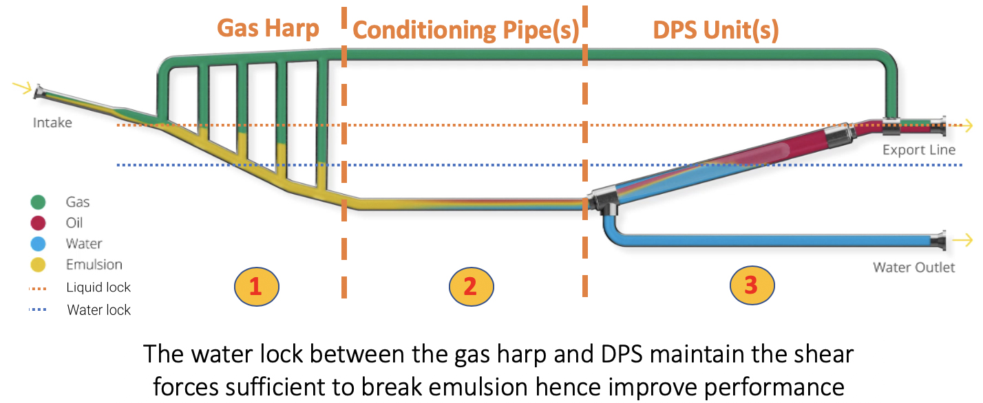
Figure 2. An artistic view of our separation system
Gas Harp
The Gas Harp is a technology developed by Norsk Hydro, now Equinor, and we license the technology for them for our application in the subsea domain. The Gast Harp is operationally proven and at TRL7 for subsea applications.
The main function of the Gas Harp is to remove the energy from slugging operations and to remove the gas flow from the next stages of separation. The slugging energy is handled by the gas and liquid interfaces in the Gas Harp working as shock absorbers, i.e. moving up and down. The gas is routed over the top of the Gas Harp and thus taken away from the further separation process. Th gas can be spiked in with the gas in a mixing tank downstream of the DPS units, before joint export to a central processing facility.
After the Gas Harp the liquid stream will be water and oil only entering into the Conditioning Pipe.
Conditioning Pipe
The DPS System is set up with one Conditioning Pipe per inclined DPS separator unit. The liquid flow from the Gas Harp will be distributed evenly from a header and into the various Conditioning Pipes.
The liquid flow velocity will be maximum 1,5 m/s and we will at the end of the Conditioning Pipe have achieve layered flow of water and oil, something that makes the separation process in the DPS units more efficient.
The length of Conditioning Pipe section required is based on several studies with 7 different types of crudes, where a test loop measured the quality of separation and flow regime at set points along the pipe section.
Dual Pipe Separator units
The DPS units are placed in parallel according to the required capacity the with an inclination of 15°. Each DPS unit can handle 15 000 bbls/day of liquid capacity (corresponds to the 1,5 m/s liquid flow velocity).The layered flow of water and oil is flowing into the 6” diameter inlet section of a DPS unit, before the inner pipe section in the DPS tapers off to 18” diameter, and finally the oil is flowing into the 30” diameter outer DPS pipe through 75mm perforations and into the oil zone above the interface level. The water is directed through 75 mm perforations below the interface level and into the water zone.
The 15° inclination assist the separation even further my setting up a velocity difference between oil and water of up to 1 m/s, where the oil is the faster liquid due to gravity forces. This difference in velocity breaks down the dispertion band between the two fluid very rapidly and we are left with to very clean liquid streams.
Separation performance
We have achieved and can deliver process quality as follows;
– Water in Oil << 30 ppm
– Oil in Water < 0,5 % BSW
– Water cut levels 0 – 95 %
– Turn down 0 – 100 %
– Gas Harp design according to defined prevailing terrain slug
– DPS unit 15 000 bbls/day liquid capacity (4 DPS unit è 60 000 bbls/day)
Conclusion
The crux with our system is that we control the flow and place ourselves as early in the flow as possible, before the oil, gas and water has been depressurized and mixed. I.e. we handle the separation process before the liquids have been depressurized, where the liquid pH is changed, small gas bubbles are mixed into the water and oil phases. The small gas bubbles are one of the major challenges that we avoid by managing our separation process the way we do.