
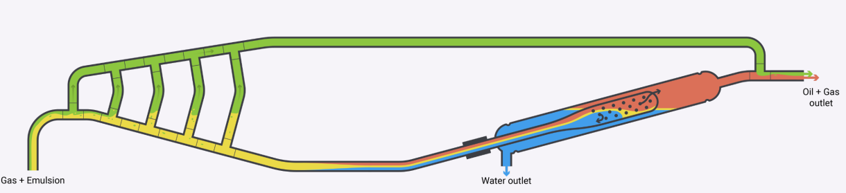
A subsea processing module is normally installed downstream of the subsea manifold that houses the subsea choke. In the pipeline between the subsea manifold and the Dual Pipe Separator (DPS) module, the flow behaviour will normally be stratified or with slugs. Our subsea separation system comprises of three major parts; Gas Harp, Conditioning Pipe and the Dual Pipe Separator.
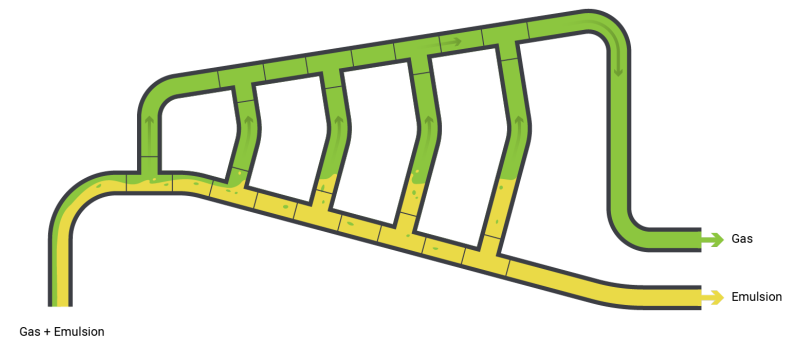
Gas harp
The Gas Harp has two important functions;
• Diverting the free gas from the DPS, and
• Suppressing the energy from the liquid slugs that typically have a pulsating flow behaviour.
The Gas Harp is the same unit that is installed at the Petrobras Marlim field (2 950 feet water depth).
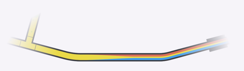
Pre-conditioning Pipeline
Downstream of the Gas Harp, the liquid flow (mix of oil and water) enters a manifold and is diverted through four identical and parallel horizontal 6´´conditioning pipes. This configuration is designed to enhance the separation of oil and water. Through testing and qualification, it has been verified that the transportation of oil and water in a 6´´conditioning pipe requires only a 12-14 meters section to establish a layered flow (oil on top, water at the bottom) and thus prepare the flow regime for the DPS.
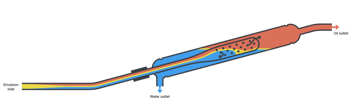
Dual Pipe Separator
Inside the tilted DPS, the diameter of the inner pipe increases from 6” to 18”. The conical shape combined with gravity triggers an interesting effect: The velocity of the oil increases, and the water slows down. As a result of this difference in velocity, a boost in separation quality occurs.
This is exactly what Professor S. Hartland (University of Switzerland) predicted when he presented his “Dispersion band theory”.
During the our qualification testing in Equinor, Porsgrunn, we were able to document up to 50 % increase of separation performance due to this difference in velocity between the oil and water.
The water and the oil exits the perforated end of the 18’’ inner pipe in two different directions;
• The water exits the inner pipe through the lower end before being drained off the DPS through a low point water outlet in the outer pipe, and
• The oil exits the inner pipe thought the upper end and then flows unrestricted out of the top of the DPS. The oil is then combined and blended with the gas bypassed from the Gas Harp. This oil and gas blend is ready for further transport to topside facilities.
The overall system design enables bypass of gas for reuse in oil transport, and provides a system for decanting water of high quality.
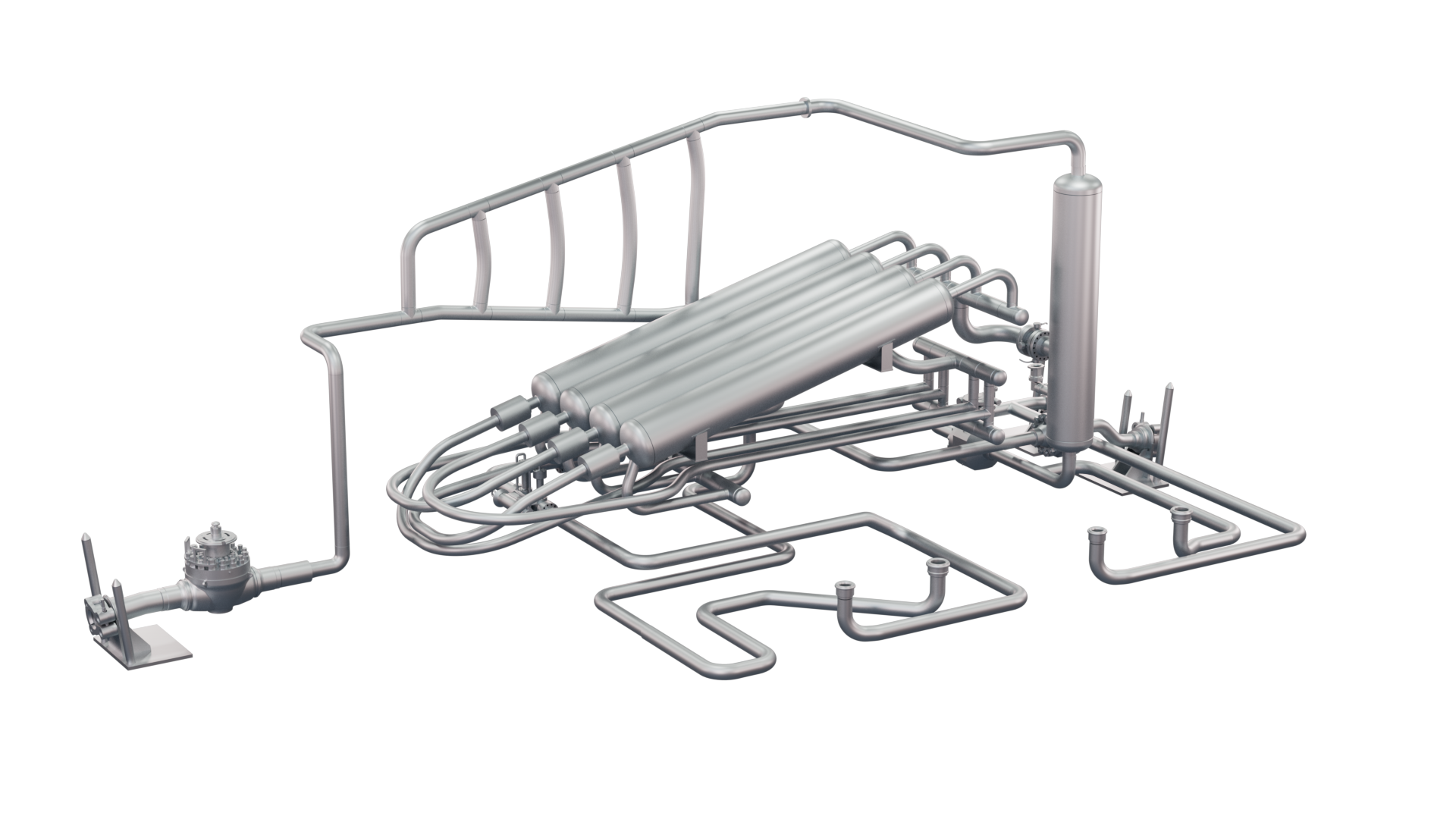
Our Scope of Delivery
Seabed Separation will, as part of a delivery, take the responsibility for the separation of the well fluids and remove the water from the well stream. Our scope of delivery can be seen on the illustration, here showing an installation with four DPS units ready to process 60.000 BPD.
The subsea module with all relevant components will be the responsibility of the engineering company handling to overall delivery.
Note the vertical vessel that is part of the delivery. This vessel has an important function for the overall system. First it will serve as a mixing point for the gas and the oil. Secondly it serves as a pressure equalizer between the gas phase and the liquid phase. By this function it contributes to minimize the overall pressure drop.
The reason is that it is commonly known that even a small pressure drop generates small gas bubbles which can reduce the separation of the oil and the water.
The gas bubbles typically form a barrier that reduce the natural coalescence within the phases.
Process quality
The figures below present the results from the testing and qualification with real oil at Equinor’s multi-phase flow loop at Herøya in Norway. In the test, a live Troll Blend crude oil was used, and the test set-up was identical to a subsea installation configuration to ensure it was as realistic as possible.
The produced water is of high quality, having a very low concentration of dispersed oil. The slight increase in concentration of oil in the produced water at high water cut, is due to a closed loop phenomenon frequently observed in the flow loop.
A water polishing technology might be installed after the DPS water outlet to ensure highest possible quality of produced water.
The quality of the produced oil is at most times at export specifications and more than good enough to enter directly into the topside separation process.
By using the DPS, the separation of water from oil is performed without any pressure drop or use of technology that creates turbulence. This gentle handling of the fluids, without exposing them to large volumes of gas bubbles, makes the great results possible.
FAQ
How is it possible to achieve such good results both on the oil side and the water side?
Past experience and testing has shown that the best separator for separation of oil and water is a pipeline. Professor S. Hartland, University of Switzerland, discovered that if the transport of the oil and the water in a pipeline can be performed having a velocity difference between the phases, the separation will occur very quick (known as The Dispersion Band Theory).
The DPS system is based on three building blocks:
- The Gas Harp for slug suppression and free gas removal, bypassing the separator and recombined with the clean oil downstream the DPS
- The conditioning 6’’ pipeline perform, as a constant liquid filled pipe, the pre-separation of the oil and the water and creating a layered flow.
- The tilted DPS unit that receive the pre-separated oil and water have a unique inner pipe (the reason behind pipe in pipe-dual pipe name) that expand from 6’’ to 18’’. The expansion further increases the velocity difference between the oil and the water to approx. 1 m/s hence boost the separation.
When the gas is removed the velocity and further energy dissipation (turbulence) is removed ending up with a controlled flow in the 6’’ pipe system and the DPS. The result, good oil and water quality, is achieved.
In the past the industry has tried subsea separation at Troll Pilot and Tordis. How come that the Dual Pipe Separator should be better?
A simple answer to that is our principle of controlling the flow and prepare for three phase separation.
The use of a conventional separator is very challenging both topside and subsea since the separator receive a well stream with a very high level of inlet energy (momentum). This inlet energy must be absorbed and stopped before the separation process starts.
Such energy absorption in conventional systems introduces large shear forces and a pressure drop, hence creation vast volume of small gas bubbles in the liquids. The gas bubbles occupy space in the liquid zone, released in the water the gas bubble will be water coated and thereby lift water into the oil (buoyancy effect) making separation a big challenge.
Another phenomenon, experience and verified by Norsk Hydro, is production from different wells with different water cuts. If a water continuous flow is mixed with an oil continuous flow from a different well into the pipeline, a strange phenomenon occurs. The creation of stable multiple dispersions.
Norsk Hydro proved that increased shear force is needed to destabilise these multiple dispersions. This is very much in line with Professor S. Hartland’s dispersion band theory.
To be able toconsistently be able to destabilise this situation with incoming stable dispersions, the DPS system is set up with the water lock.
The water lock function and effect were verified during the Equinor test.
The test was performed using Troll oil. What about other oils will that change the performance?
It is correct that Troll Blend was tested at 30 bar pressure and 60 C temperature showing very good results.
Earlier testing and qualification work done by Norsk Hydro have shown the same effects with different oil types. During the development and testing of the Norsk Hydro pipe separator 6 different oils were tested, ranging from API 16 and higher.
The experience and results showed that very good quality of both phases, oil and water, were achieved. In principle it proved that separation in a pipe is unique and it does not need long time before the phases are separated and with good quality.
During our qualification a CFD analysis was performed, based on real oil data, showing the transportation of oil and water in a 6’’ pipeline needed 12-14 meters to achieve complete separation and a layered flow regime.
The DPS system is built on a 6’’ pipeline designed for 15000 BPD. If the liquid flow is higher parallel systems will be used. I.e. four DPS pipes will be able to handle 60 000 BPD.
What about sand and sediments? That will always be a problem.
Experience from a large number of installations have shown that most of the sand and sediments are transported with the oil. The particle size, affinity to oil and the viscosity of the oil typically embed the particles in the oil phase.
The DPS system is designed to minimise the risk for sediment settling and accumulation or blockage by including a sand trap at the inlet for accumulation of coarser particles. The perforations in the inner pipe of the DPS have an opening of typically 75mm. The water outlet is a 6’’ opening designed without any pockets and at the lowest point in the system.
In principle the entire system is like a pipeline system designed for constant transportation of phases.
This is supported with feedback from offshore installations where the fines deposits become a challenge in the 2nd or 3rd stage of the separation and stabilisation of the oil.
We have experienced server slugging in our system. Is the gas Harp able to handle large terrain induced slug?
Large slugs of liquids will be a challenge and often due to high arrival velocity.
A standard DPS system is based on a 60 000 BPD operation. During verification of the Gas Harp and the DPS System CFD analysis showed that the liquid carry-over in the Gas Harp occurred at approx. 105 000 BPD (high liquid velocity). I.e. well above our design envelope.
If severe terrain slug is an issue installing parallel Gas Harps is recommended.
Dual Pipe Separator
The animation shows an oil installation with the pipeline and infrastructure in place.
This can be from a brownfield installation but even apply used on a greenfield application.
- The DPS module is lowered at the seafloor and connected to the pipeline using the pre-installed connection points.
- The water pump (WP) is lowered into its docking station to serve the function for water removal from the DPS module either for re-injection into the reservoir or a well dedicated for this removed water. It is possible to use the pump together with a water polishing technology prior to subsurface discharge of the produced water
- The subsea separation will now serve as a first phase IOR tool since the water is removed hence less flow resistance in the further lifting of the oil.
- The next step, after some time, is installation of the Multi Phase Pump (MPP). Having the MPP in operation the operational pressure on the subsea station can be reduced and phase two IOR achieved. An operational pressure of I.E. 10 bar can easily be maintained if requested.
Such a stepwise procedure, if selected, will follow the normal production profile but provide a stepwise increase in the oil production.
Another effect can be reduction in CAPEX (CAPital EXpenditure) since the MPP can be put in place after x-number of years and put on the OPEX (Operational EXpenditure) instead.