How do we handle production testing in parallel with normal production?
Introduction
Well testing is performed to verify individual well performance and to obtain information used for allocation. There are many different methods used, the most common is to utilize the test separator installed at the topside facility. Over the last 15 years the development and installation of multiphase meters to access the needed information has led to installation of multiphase meters on the template (subsea) and on production risers topside. This is a way to increase the overall understanding of well behavior, but experience shows that the accuracy is not what it should be. Best practice is considered to be +/- 5 % measurement accuracy. One example is the use of lifting gas to maintain well production. Introduction of the lifting gas, which has a different composition compared to the reservoir gas, increase inaccuracy.
The oil companies have asked Seabed Separation to come up with a solution based on the Dual Pipe Separator principle to increase and ease the operation by separating the well fluids and perform single phase metering. . When the production testing is performed in parallel with and without stop of the normal production from the other wells at the template, the economic will be very interesting.
Principle of operation
What makes the DPS system possible to perform dual operation – testing and production?
Let us start with the design and principle of operation.
The illustration (figure 1) below show the DPS system as designed to incorporate the gas harp in cooperation with the other components. The well stream enters the gas harp where the gas is separated from the well stream. As seen on the below illustration (figure 1) the green colored section is occupied by the gas which is separated and can be metered as a single gas phase. The liquids are further processed in the conditioning pipe and finally separated in the tilted DPS. The water (blue) is a separate as a single phase and can be metered, the same with the clean oil (red) leaving the top of the DPS.
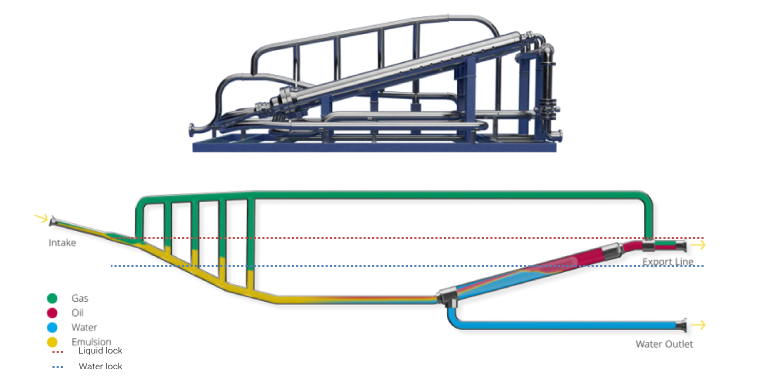
Figure 1. An illustration of the DPS system
On figure 2 below, the sketch shows the DPS units that can be converted into two individual systems. The split is done by closing the valves between the section having three DPS (production section) and the section having two DPS (test section). During “normal” operation both sections are in operation receiving fluids in both lines and operates as one system. A more correct description is shown on the P&ID (figure 3) below.
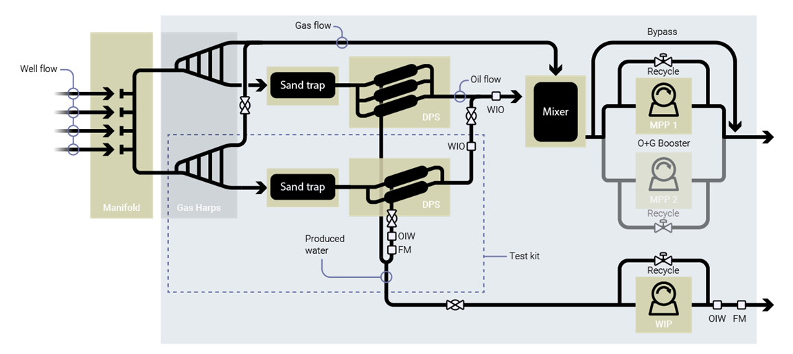
Figure 2: Principle sketch of combined test function and continuous production
The subsea module is set up with one multi-phase pump and one water injection pump that during normal operation handle the DPS system downstream requirement, boosting of combined oil and gas to the platform and removal of the water from the DPS for injection into the ground.
Having these pumps in place the conversion from normal operation into a combined test and operation mode is possible. The multi-phase pump will be operated as normal based on the volume of oil and gas in the mixer (level controlled). The multi-phase pump will respond to the measured level in the mixer by receiving oil and gas from both the test section and the normal production section, by varying the pump speed to keep the correct level in the mixing tank.
The operation of the test section with single phase metering will be explained using the P&ID as reference (figure 3)
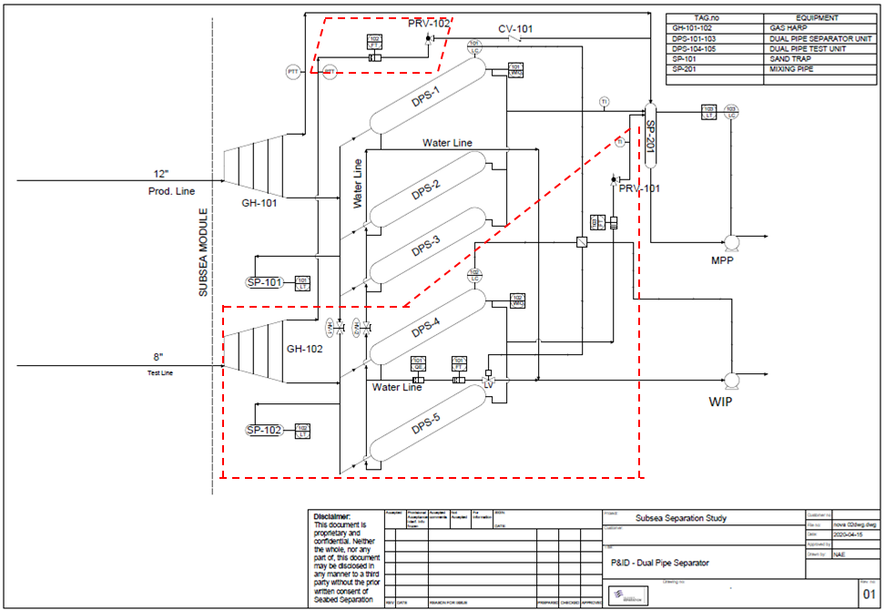
Figure 3: P&ID with components for the test section specified in the red area
On the P&ID the test section is highlighted in the red dotted boxes
During test operation the valve on the inlet manifold is closed, segregating the three DPS for normal operation and the two DPS for test operation. On the water outlet manifold a valve is closed creating a similar segregation. On the test section oil outlet pipeline a valve giving a back-pressure function is activated (PRV-101). This valve will operate in a mode that regulate its opening dependent on the actual pressure in the mixer. A similar valve (PRV-102) is positioned on the gas outlet pipeline downstream the gas harp having a similar operation as the oil outlet valve.
The test section water part is operated by a control valve that receives signals from the test section water interphase instrument and operate in cascade modus with the signals from the interphase instrument on the production section. I.e. if the water level in the test section increases the water valve on the test section will open, but at the same time a signal is sent to the cascade regulator that send a signal to the water injection pump to increase the speed. This combined operation allows for interphase control and water handling of two independent systems.
The clean single phases, gas – oil – water, are metered and quality controlled using on-line instruments that transmit the information to the platform. Using this system and methodology each well stream can be quantified, an operation controlled from the platform central control room.
When the testing operation is completed the valves segregating the two sections are opened and normal production commence. The system that is shown on the P&ID is designed to handle 75.000 BPD in full service and a well that can produce 30.000 BPD as maximum during well test.
Conclusion
Since the DPS system is designed as individual separators and has a defined throughput it makes it easy to combine the units in different ways, test operation being one. The oil company request for increased accuracy in phase measurement can easier be done and an accuracy level of +/- 1% is within reach.
As an example, for a 60 000 BOPD field (50 USD/bbl) this will have an impact of potentially 10,8 mill USD per % improvement in measurement accuracy